Overview
Verilog, Verilog-A, and Verilog-AMS are hardware description languages, and are collectively referred to in this document with Verilog-A/MS. Verilog is suitable for describing digital systems, Verilog-A is suitable for describing analog systems, and Verilog-AMS is suitable for describing mixed-signal systems (systems that combine analog and digital). Verilog and Verilog-A are related but distinct languages that run on different simulators. Verilog runs on logic simulators and Verilog-A runs on SPICE simulators. Verilog-AMS combines Verilog and Verilog-A and adds some additional features. It runs on AMS simulators.
Generally the Verilog languages are used for simulation, though Verilog (the digital language) is also used for synthesis. Verilog-A and Verilog-AMS are not used for synthesis.
Systems
Systems are described as a hierarchical collection of components that are interconnected with nets. The nets carry signals and represent the primary way in which the components communicate with each other. Nets pierce the boundaries of components through ports. There are three types of ports, input, output, and inout. This indicates the direction the signal travels as it traverses the port. Each component is an instance of a module and a module acts as the component definition. The top of the component hierarchy is referred to as the top-level module. A top-level module is a module that is included in the system but is not instantiated by any other modules. There may be more than one top-level module in a system, and collectively they generally act as the testbench for the system. For example:
`timescale 1ns/1ps

module dff(q, d, clk);
   output q;
   input clk, d;
   reg q;

   always @(posedge clk) q = d;
endmodule

module dff_tb;
   wire clk, clk2, clk4;
   assign #1 clk = (clk === 0);
   initial #10 $finish();

   dff FF1(.q(clk2), .clk(clk), .d(clk2));
   dff FF2(.q(clk4), .clk(clk2), .d(clk4));
endmodule
In this example there are two modules, dff, which defines a D flip flop and
dff_tb, which defines a testbench for the D flip flop. dff_tb
instantiates two copies of dff but is not instantiated by any module in the
system, and so dff_tb is a top-level module. The system consists of
a top-level module, dff_tb, which further contains two instances of dff,
named FF1 and FF2. There are three nets, clk, clk2, and clk4
that are used to pass signals between the components. They are declared as wires
in dff_tb. Wires are a type of net that can take any of four values: 0, 1,
x (unknown), or z (undriven). clk is driven by the assign statement
within dff_tb. clk2 is driven by FF1 and clk4 is driven by
FF2.
Signals
The Verilog languages supports two different types of signals: discrete and continuous.
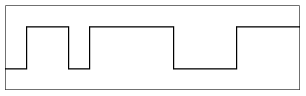
Discrete signals are signals that are constrained to be piecewise constant, meaning that their values cannot change except at a finite number of discrete points in time, at which point their value changes abruptly. The changes in a discrete signal are referred to as events. There are two kinds. Digital discrete signals only allow for 4 possible values: 0, 1, x, and z.
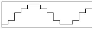
Real discrete signals can take on any real value.
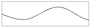
Continuous signals are signals that can change continuously. It may be that as a result of the details of the system being represented that continuous signals contain discontinuities and perhaps are even piecewise constant, but they would still be considered to be continuous because the language itself allows their values to vary continuously with time. Discontinuities in continuous signals are not considered events.
In Verilog, all signals are discrete and digital. In Verilog-A, all signals are continuous. Verilog-AMS, being the merger of Verilog and Verilog-A, supports both discrete and continuous signals and allow both digital and real discrete signals. As such, Verilog-AMS is often referred to as a mixed-signal language.
The Verilog-AMS language is said to have two contexts: a discrete context and a continuous context. The discrete context describes content destined for the discrete kernel and the continuous context generates describes content destined for the continuous kernel.
Verilog-AMS simulators are said to have two kernels: a discrete kernel and a continuous kernel. The discrete kernel, also known as the event driven kernel, simulates the portion of the system described in the discrete context. The continuous kernel, also known as the SPICE kernel, simulates the portion of the system described in the continuous context.